|
|
 Author Author |
 THE HAYACCINO (currently 594 views) THE HAYACCINO (currently 594 views) |
| GR1 |
| Posted on: Wednesday, February 23rd, 2011, 3:40:37am |
  |
|
|
"You'll have more fun in an imperfect car than you will in an unfinished one!"
I start the thread with Wayne2105's sentence that perfectly describes my objective (as I am 57 years old!) when I embarked on a very challenging project - to put the Hayabusa engine in the Cappuccino - but in the passenger compartment!
In 2008 I read about Davidmotec's Hayabusa project that had left me speechless and it wasn't until a year later, when, after having acquired the slightly damaged Cap (for parts) I realised that, as the chassis was still square, I could do something else with it!
Borrowed the Hayabusa engine from a friend and with my mechanic (Tony Flood of Tony Flood Motorsports), after looking at several options, decided to have a permanently fixed passenger - the Hayabusa!.
The engine (2005 with 4750 kms) came from Melbourne and the story begun...
First thing to do was to cut the floor and, as the engine will retain the standard airbox, two air-intake holes that will get the air from the bonnet mounted scoop. |
Last modified Wednesday, February 23rd, 2011, 4:02:56am by GR1 |
|
 Logged Logged |
|
|
|
|
| GR1 |
| Posted on: Wednesday, February 23rd, 2011, 4:08:55am |
|
|
|
Reinforced accross the floor, with the shifter (lever only) and handbrake retained from standard Cap.
As the engine will have to be fully enclosed from the driver, the idea was to have cooling air coming through the tunnel, cool the gearbox and escape through the back of the hole and through the 4 holes drilled in the back "firewall" as the exhaust would be there as well. |
|
| Logged |
|
|
 |
Reply: 1 - 26 |
|
|
| GR1 |
Posted on: Wednesday, February 23rd, 2011, 4:13:08am
 Attachment: pic_0202_108.jpg - 111.70 KB (602 views) Attachment: pic_0202_108.jpg - 111.70 KB (602 views) |
|
|
|
| pic was too big |
 |
|
| Logged |
|
|
|
Reply: 2 - 26 |
|
|
| GR1 |
| Posted on: Wednesday, February 23rd, 2011, 4:44:25am |
|
|
|
Long discussions and research followed to decide the type of sump considering the engine orientation and the G forces it will be subjected to.
Finally it was the dry sump by Nova Racing Transmissions with baffles and the oil pump.
With new gasket and quite good instructions, mounting was straight forward and relatively easy.
As the left part of the tunnel was cut out, Tony welded a reinforcement (blue square tube) member as well as brackets for the Hayabusa original mounting brackets and it started to get some shape and real "meaning". |
|
| Logged |
|
|
|
Reply: 3 - 26 |
|
|
| GR1 |
Posted on: Wednesday, February 23rd, 2011, 4:48:26am
Attachment: untitled12.jpg - 34.84 KB (598 views) |
|
|
|
| pics |
 |
|
| Logged |
|
|
|
Reply: 4 - 26 |
|
|
| GR1 |
Posted on: Wednesday, February 23rd, 2011, 4:50:09am
Attachment: untitled15.jpg - 91.71 KB (594 views) |
|
|
|
| and from above... |
 |
|
| Logged |
|
|
|
Reply: 5 - 26 |
|
|
| Erik |
| Posted on: Wednesday, February 23rd, 2011, 12:36:28pm |
|
|
|
And I thought that restoring a Cappuccino was quite a project...
From what I can see in the last picture you'll need to reroute the exhaust though 
Nice work! |
|
| Logged |
|
|
|
Reply: 6 - 26 |
|
|
| GR1 |
Posted on: Thursday, February 24th, 2011, 3:33:38am
Attachment: exhaust1.jpg - 139.29 KB (552 views) |
|
|
|
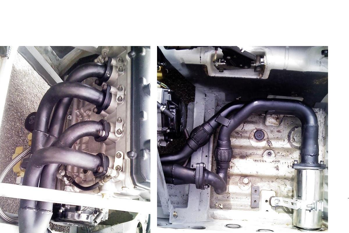
Very true!
The most practical (and least expensive) was the sideways exhaust with a straight through muffler exiting through the sill.
The ports fittings from the original exhaust were cut out and welded to the pipes; primaries about 10" and 2ndaries about 20" (from the fading memory).
The whole system is quite robust, looks a bit "agricultural" what, considering it will be covered, didn't matter to me. For 3 times as much money I could have got a better looking and, possibly, 3% better perfoming ehaust... |
 |
|
| Logged |
|
|
|
Reply: 7 - 26 |
|
|
| GR1 |
Posted on: Thursday, February 24th, 2011, 3:38:46am
Attachment: exhaust2.jpg - 161.96 KB (549 views) |
|
|
|
| So, at the end of the day, the exhaust looked like this. |
 |
|
| Logged |
|
|
|
Reply: 8 - 26 |
|
|
| kayfour |
| Posted on: Thursday, February 24th, 2011, 12:12:33pm |
|
|
|
I am liking this build thread very much
got to put up more pictures!
|
|
| Logged |
|
|
|
Reply: 9 - 26 |
|
|
| Coolrace91 |
| Posted on: Thursday, February 24th, 2011, 6:15:33pm |
|
|
|
What a crazy idea  . .
When you will drive, the engine noise will be so strong... 
|
|
| Logged |
|
|
|
Reply: 10 - 26 |
|
|
| GR1 |
Posted on: Friday, February 25th, 2011, 2:51:04am
Attachment: untitled22.jpg - 103.69 KB (514 views) |
|
|
|
"When you will drive, the engine noise will be so strong... "
That's what I was thinking as well - and very hot - I thought!
So I ordered the EZ COOL Insulation from the Harbour Supply, in US, which, as stated, is used in ()at least some) NASCARs for heat and noise insulation.
The insulation would go inside the engine enclosure (I called it NED KELLY - you will see why); easy to glue on and very easy to cut and shape with scissors.
That part is coming later...
Now: THE DRIVETRAIN - BIG PROBLEM.
With the Cap diff ratio of 5.2 the car would be almost impossible to start moving (would dart and probbably stall) and the max speed would be not much more than 140 km/h.
Finding the right diff involved lot of calculations and research and, luckily, Tony had a Celica GT4 Torsen diff with ratio of 2.9, giving me normal start and the (theoretical) top speed of 240 km/h (nice, isn't it?).
On the other, engine end, another BIG problem!
To access the output shaft, the clutch cover and the slave cylinder had to be replaced with a suitable substitute which, apart from de/clutching, will allow linking the output shaft to the propeller shaft.
All reasonably priced (that I was able to find) aftermarhet parts are made for the CHAIN driven shafts and some mods/arrangements will have to be made to attach the prop shaft to the output shaft.
After installing the clutch slave cylinder it looked like below.
|
 |
|
| Logged |
|
|
|
Reply: 11 - 26 |
|
|
| Ricou |
| Posted on: Friday, February 25th, 2011, 4:07:25am |
|
|
Maximum Member

Posts: 1110
Posts Per Day: 0.65 |
|
Wow, what a great project !
Good luck and keep the pics coming  |
|
| Logged |
|
|
 |
Reply: 12 - 26 |
|
|
| GR2 |
Posted on: Monday, February 28th, 2011, 7:58:37am
Attachment: untitled33.jpg - 109.07 KB (474 views) |
|
|
|
To make a SPLINED coupling that will fit onto the output shaft proved to be extremely expensive and complicated, which pointed to the chain sprocket with 8 holes in it.
A cylindrically shaped adapter with 2 flanges (all in one piece) one attached to the sprocket with 8 bolts and the prop shaft yoke attached to the other side.
The adapter had to be hollow to secure it by a 32mm nut onto the output shaft, with external dimensions to clear the clutch slave housing and still be strong enough to take all the loads (the chain sprocket will be a weak point here - so no burnouts nor "full" throttle starts. Put in the picture the attachment for and the push-pull cable for the shifter cramped with clutch hydraulic hose - and you will get something like this: |
 |
|
| Logged |
|
|
|
Reply: 13 - 26 |
|
|
| GR2 |
Posted on: Monday, February 28th, 2011, 8:10:42am
Attachment: ned_kelly.jpg - 79.36 KB (472 views) |
|
|
|
In the meantime I spread out the loom and following an excellent wiring diagram (colour coded) from Clymer service manual, labelled all plugs and sockets to know what's going where (no chance of mixing as no plugs are the same).
The time is now for the engine enclosure as it has to be well separated from the driver.
It took good money (from me) and much less time for an enthusiastic and an excellent sheet metal expert to make what I call "Ned Kelly" (see the photo and for those who don't know - Google this name and you will see why - ).
Although quite high, the visibility was not restricted at all.
|
 |
|
| Logged |
|
|
|
Reply: 14 - 26 |
|
|
| GR2 |
Posted on: Monday, February 28th, 2011, 8:14:21am
Attachment: untitled44.jpg - 131.75 KB (471 views) |
|
|
|
I must admit - a pain to remove and a nightmare to assemble - Bernie from Cockburn Sheet Metal made it a fantastic fit!
Now "bandage" the exhaust, glue the insulation inside Ned and the exhaust side of the tunnel.
Fit the air ducts from the holes in the firewall to the airbox (that was far from easy) |
 |
Last modified Monday, February 28th, 2011, 8:16:18am by GR2 |
|
| Logged |
|
|
|
Reply: 15 - 26 |
|
|
| GR1 |
Posted on: Tuesday, March 1st, 2011, 4:53:47am
Attachment: untitled55.jpg - 93.58 KB (451 views) |
|
|
|
The diff was well different from the standard and new diff bracket was well different to fit to the rear rails, so Tony made a special fit bracket, mounted without bushes, and the rear attachment was an easy to solve.
As replacing the drive shafts would take as much time as money, we decided to keep the standard shafts what required machining the diff flanges and inserting the "ring" coupler onto the drive shafts as an "interface" between the diff flange and the driveshaft flange: |
 |
|
| Logged |
|
|
|
Reply: 16 - 26 |
|
|
| GR1 |
Posted on: Tuesday, March 1st, 2011, 5:00:44am
Attachment: untitled66.jpg - 102.37 KB (447 views) |
|
|
|
| And at the end, a tunnel brace with air scoop (to take the heat out of the exhaust side of the tunnel and to cool the diff), another air scoop to channel the under-car air into the engine compartment with 4 60mm dia holes cut in the back wall on the passenger side to let the exhaust heated air out and the Gurney lip on the front (engine) cross member to create some vacuum underneath the engine and "suck" the hot air away. |
 |
|
| Logged |
|
|
|
Reply: 17 - 26 |
|
|
| GR1 |
Posted on: Tuesday, March 1st, 2011, 5:19:59am
Attachment: untitled77.jpg - 85.28 KB (449 views) |
|
|
|
To avoid air trapping when filling the coolant and as the radiator filler neck is well below the thermostat housing, Tony invented a very clever thing.
On the top of the thermostat housing he inserted a nipple to which a breather hose was attached ending under the bonnet.
Now, when filling the coolant, I have to tilt the car (nose up) until the filler neck is above the thermostat houseing, open the breather valve (at the end of the breather hose) and fill until the coolant drips out: close the valve, close the filler and - voila!.
BTW I have the Davies Craig EWP80 installed for continuous running and after a few seal problems (that Davies Craig were quick and fair to respond to) it is all working fine.
Apart from the standard Hayabusa dash, I installed dual oil pressure and temperature gauge, gear indicator and water temperature gauge.
The fuel pressure gauge is under the bonnet in line with the fuel supply hose.
Will take few more photos of the interior and exterior over the weekend (racing in Collie) and will post here and in the "Racing Cappuccinos".
If you have any comments, questions etc, let us all know.
|
 |
|
| Logged |
|
|
|
Reply: 18 - 26 |
|
|
| GR1 |
Posted on: Tuesday, March 1st, 2011, 5:20:50am
Attachment: untitled88.jpg - 82.09 KB (447 views) |
|
|
|
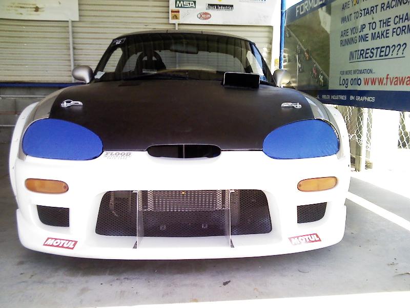
| And a "head-on" |
 |
|
| Logged |
|
|
|
Reply: 19 - 26 |
|
|
| Ricou |
| Posted on: Tuesday, March 1st, 2011, 6:07:44pm |
|
|
Maximum Member
Posts: 1110
Posts Per Day: 0.65 |
|
|
| Logged |
|
|
| |
Reply: 20 - 26 |
|
|
| lord |
| Posted on: Wednesday, March 2nd, 2011, 12:44:08am |
|
|
|
is there a video of this racing??
Have to say this is looking tasty... |
|
| Logged |
|
|
|
Reply: 21 - 26 |
|
|
| GR1 |
| Posted on: Wednesday, March 2nd, 2011, 2:26:10am |
|
|
|
There is no video of this race (and I am glad there isn't.
Due to fuel pump issues (checking the fuel level with the dipstick I hit the soft spot of the clip holding the regulator and it fell off. After a few laps the regulator was holding its hole with the skin of its teeth and finally dropped off with my "pride and joy" getting towed in the paddock with me, all perplexed, inside...
Now that sorted and fixed fuel sender, I hope this weekend hill climb and circuit sprint in Collie will be a bit better.
Will keep you posted. |
|
| Logged |
|
|
|
Reply: 22 - 26 |
|
|
| GR1 |
Posted on: Thursday, March 17th, 2011, 8:04:22am
Attachment: untitled99.jpg - 81.81 KB (351 views) |
|
|
|
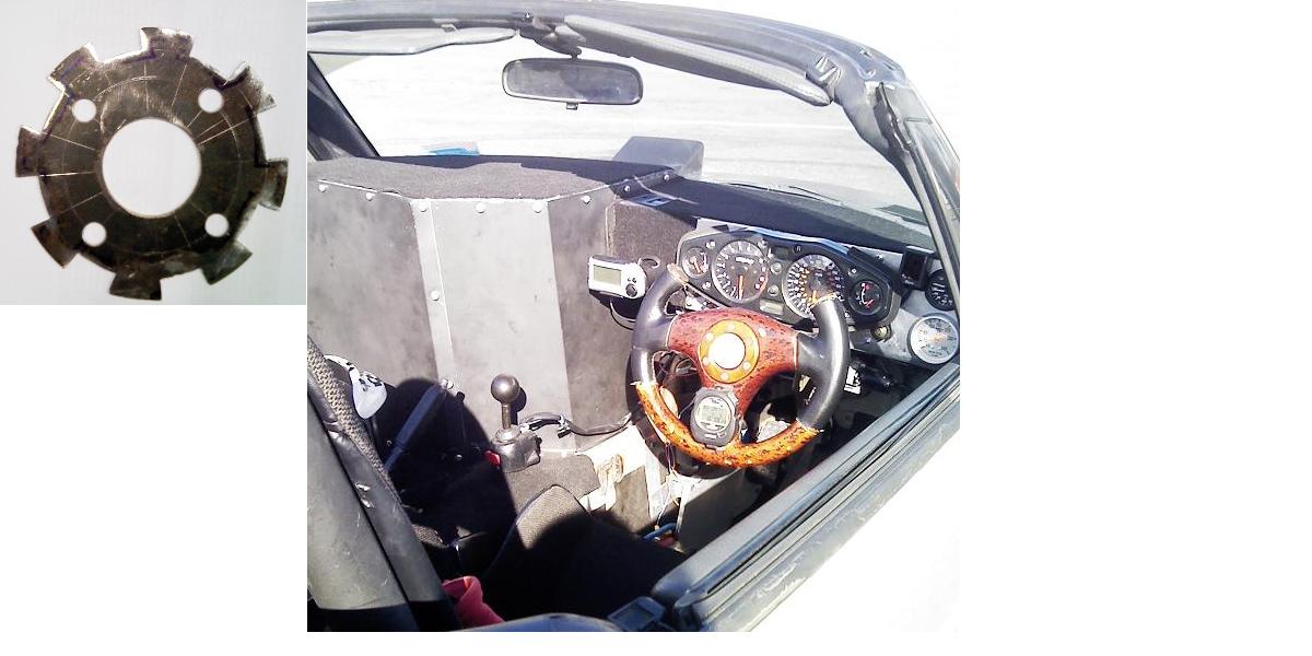
Here is a shot of the cockpit with all the current instruments.
Hayabusa standard dash (it required installation of the "chopper" disk (left in the photo) between the sprocket adaptor and the prop shaft yoke to give reading - still to calibrate), gear indicator, water temp gauge, oil press/tem dual gauge, G-Tech (cant sort the rev counter - yet) and the stopwatch on the steering wheel.
It proves I was too busy to think to activate the stopwatch or G-Tech - but it will come..., later |
 |
|
| Logged |
|
|
|
Reply: 23 - 26 |
|
|
| Ricou |
| Posted on: Thursday, March 17th, 2011, 4:47:56pm |
|
|
Maximum Member
Posts: 1110
Posts Per Day: 0.65 |
|
Good job again
But this wheel is very ugly I think. |
|
| Logged |
|
|
| |
Reply: 24 - 26 |
|
|
| mattjohns |
| Posted on: Saturday, March 19th, 2011, 1:11:55am |
|
|
Maximum Member
Posts: 1652
Posts Per Day: 0.94 |
|
“ |
Quoted from Ricou, posted Thursday, March 17th, 2011, 4:47:56pm at here |
” |
But this wheel is very ugly I think.
|
|
I agree, but then, if you are going to cut up a steering wheel you don't want to destroy a good one 
How's the visibility over Ned Kelly and how close is the gear lever? |
|
| Logged |
|
|
| |
Reply: 25 - 26 |
|
|
| GR1 |
| Posted on: Sunday, March 20th, 2011, 5:57:16am |
|
|
|
Yes, the steering wheel is ugly but it does the same thing as the "awesome looking" one and for $400 less.
Until you asked the question re the visibility over NedKelly I didn't even think about it.
So far, participating in a clockwise and anticlockwise circuits it doesn't seem to be an issue.
Likewise with the shifter: although from the photo it may look very close to the NedKelly, I was able to shift up and down without touching it.
Tested the speedo (wheel) on a (secret) road: at actual 40kmh, speedo showed 70; at 60km/h it showed 100 and at 80km/h it showed 140.
The "Monster" Lap Checker (if anyone has got/heard about it) shows the accurate speed at 20 pulses; it's now bit more testing, data analysis and eventual modifications of the speedo wheel to obtain the correct speed on the dash - will let you know. |
|
| Logged |
|
|
|
Reply: 26 - 26 |
|
|
|
 Cappuccino Owners Club › Gallery › Cappo Related Album › THE HAYACCINO (Moderators: )


 Locked Board