0 Members Browsing (1 Guests) Currently No Active Members
Pages:1
Author
More wiring questions (currently 330 views)
Nat-AJ
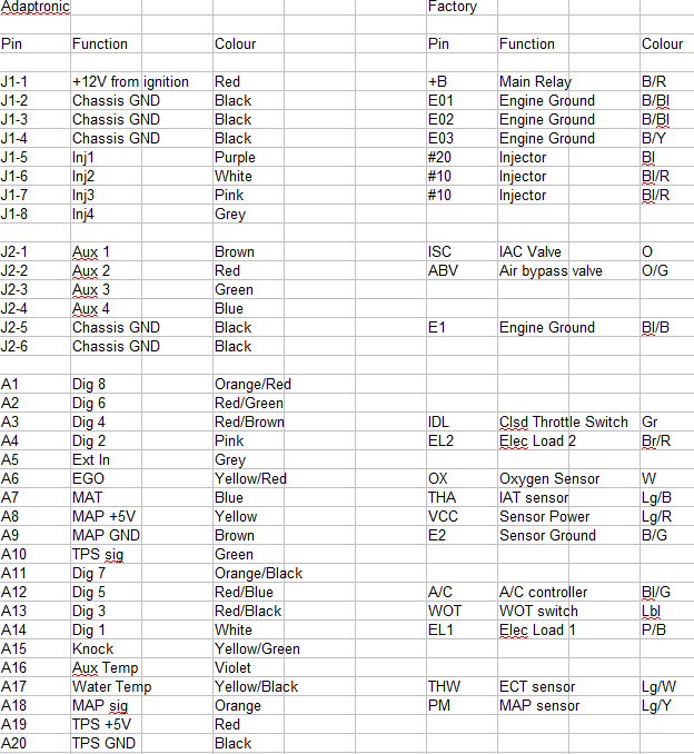
Posted on: Saturday, May 23rd, 2015, 8:52:56pm Attachment:pinout.jpg - 129.99 KB (346 views)
Guest User
Hi Guys, Finally received my E420C, and I'm currently wiring the adaptronic loom up to an old ECU socket, just had a couple of questions on bits I wasn't sure about. I'm working from the Excel file that Grant sent me.
Cannot figure out the Igniter/ignition wiring... "Via ignitor! White wire to IG, red wire to Adaptronic, BLK wire to E03" are these the "internal" wires ie Option2 ?? I already plugged the White internal wire into B4.... any easy way to remove the pins?
There seem to be a number of pins on the old ECU socket that aren't connected to the adaptronic (MON, P5V, P55, PM, DP etc.) is this correct? edit- [Just realized some of my ECU markings don't match the ones in the service manual, have cross referenced them]
INJ2 and INJ3 both connect to #10 ... is this right? - Ok, they do both run off the same one.
I picked up the nissan TPS with both Digital/analogue TPS, I'm assuming that "TPS sig" "TPS +5v" and "TPS ground" go to the analogue connector. Do I still connect the Digital WOT and IDL to the digital connector (and inputs)? - disregard, I'll hook them all up
Any other gotchas?
Thanks, I'm sure I will have more questions as I progress, but will scour the forums first.
Last modified Sunday, May 24th, 2015, 8:07:35pm by Nat-AJ
About the TPS, no, you don't need the digital switches if you have an analogue TPS hooked up.
Logged
Reply: 1 - 6
Nat-AJ
Posted on: Monday, May 25th, 2015, 2:23:24pm
Guest User
thanks Ricou
I think I'm getting my head around the igniter, the thing that confused me is mine has connections for 4 wires (additional Ground?) , but didn't come with any connected...just a pin key
Pin1= to coil negative Pin2=Ground Pin3=+12v ingnition live Pin4=Input from ECU
but i'm not sure which would represent the red, white and black wires on a 3-wire igniter.
I would have thought the "IG" on the original ECU makes and breaks the Negative connection to the coil...but then why would I need a +12v if this is going straight to the coil from elsewhere???
Logged
Reply: 2 - 6
Nat-AJ
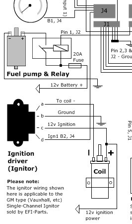
Posted on: Monday, May 25th, 2015, 3:30:48pm Attachment:igniter.jpg - 29.58 KB (319 views)
Guest User
OK, so i just found this on the EFI-parts website. Seems a little odd, but I assume the 3-wire igniters do not have a +12v going to the coil. It mentions GM igniter setup, could this cause any problems if I wire-up like this?
The 4th connection of the 3 wire ignitor is the metal body of the ignitor being earthed to the chasis. They usually come with heat paste as well. Yes it switches the negative from the ignition coil to ground and you need it to do this as the ecu cannot handle the current.
Logged
Reply: 4 - 6
Nat-AJ
Posted on: Tuesday, May 26th, 2015, 8:12:12pm
Guest User
thanks Grant, I think i'm pretty much there with the wiring...just the analogue TPS and knock sensor to go, I should be able to figure these out.
New question, not found this anywhere... The E420C i have is a 2nd hand one, I had a horrible thought that because it is so configurable, the existing outputs etc could be set to anything (not sure what car it was on before) Is there a way of wiping/reseting the existing firmware/maps before turning the ignition key ?? Ideally i'd like to load one of the .ecu files I have from an existing cappo before I even send power to it.
I guess I could hook up a 12v powersupply to the B+, but seems a messy way to do it. I cant imagine it will connect to the laptop serial at all without power though
DOH- just found it... 2.0. Basic Setup Once the wiring is done, connect the white 8 pin plug to the ECU (and ONLY the white 8 pin plug). This should power up the ECU which should then be connected to a PC using a straight through RS232 DE9 extension (male-female) cable. WARI, the Windows Adaptronic Remote Interrogator, should be run on the PC, and the COM port should be selected. • Verify that WARI can see the ECU (a message such as "ECU connected Adaptronic V1" should appear, rather than "No ECU connected") • Make sure the settings are all ready from the ECU (when first connected, a message such as "Reading Settings 0%" should appear, and when this reaches 100% and the message changes to "ECU connected", the settings have all been read). Once the ECU is online, you should then begin by configuring the basic setup
Last modified Tuesday, May 26th, 2015, 8:27:15pm by Nat-AJ
Logged
Reply: 5 - 6
kash
Posted on: Monday, March 7th, 2016, 6:05:29pm
Guest User
Hi Nat,
How are you getting on with the Adaptronic? I'm considering embarking on the same journey and was looking for some info on the general day-to-day living with the replacement ECU.
 Cappuccino Owners Club › Specific Discussion Boards › Adaptronic ECU › More wiring questions (Moderators: )
 Author
 More wiring questions (currently 330 views)


 Attachment:

 Logged